1. Understand Rivet Anatomy and Key Dimensions
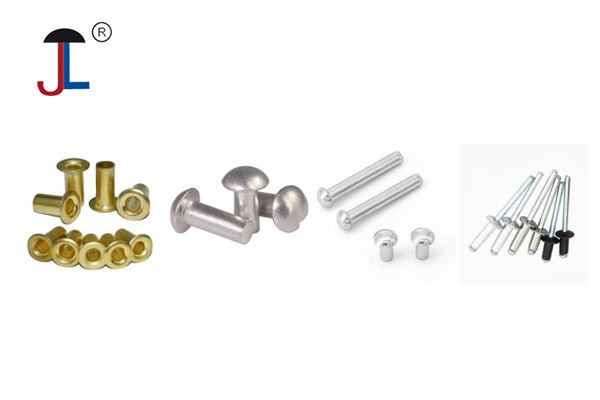
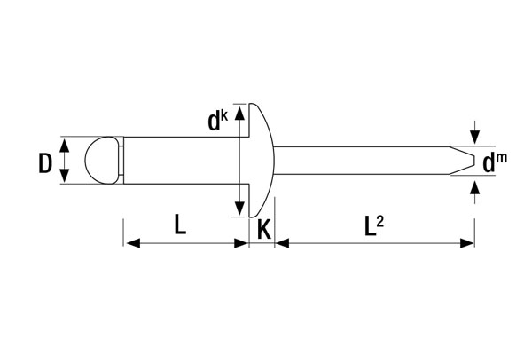
Before measuring anything, it helps to know the basic parts of a solid or semi‐tubular rivet:
-
Head
-
Type: Common head styles include dome (also called “universal” or “raised”), countersunk (flat), flush, or large‐flange heads.
-
Head Diameter (Dₕ): For a dome head, this is the maximum diameter across the curved top. For a countersunk head, it’s the diameter of the flat, angled portion designed to sit flush in a beveled hole.
-
Head Height (Hₕ): The distance from the underside of the head to the very top of the dome (for dome heads), or the thickness of the head at its tallest point.
-
-
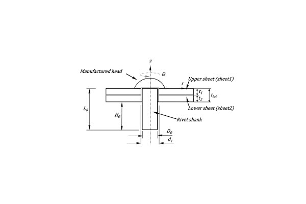
Shank (or Body)
-
Shank Diameter (Dₛ): Often called the “rivet diameter.” This is the diameter of the cylindrical portion beneath the head.
-
Grip Length (Lₛ): Measured from the underside of the head to the tip of the un‐deformed rivet. This is sometimes simply referred to as the “rivet length.” It dictates the maximum combined thickness of the materials you can fasten (i.e., the grip range).
-
-
Mandrel (for Blind/Pop Rivets)
-
Mandrel Diameter and Length: Only relevant if you’re dealing with blind (pop) rivets, whose mandrel protrudes from the blind side until installation. For measuring an uninstalled blind rivet, you typically ignore mandrel length and focus on the grip range (which is stamped on the rivet’s packaging).
-
-
Grip Range (Gₛ)
-
This is the range of material thicknesses that the rivet was designed to clamp. On blind rivets, grip ranges are given as a minimum and maximum thickness (e.g. 1.5–3.2 mm).
-
In practice, most specifications ask for:
-
Rivet Diameter (Dₛ)
-
Rivet Length (Lₛ) (measured under the head)
-
Head Style and Dimensions (if head size matters for countersinking or clearance)
-
Material and Strength Grade (e.g., aluminum, steel, stainless steel—but that’s beyond purely dimensional measurement).
2. Tools and Equipment You’ll Need
-
Calipers (Digital or Vernier)
-
To measure diameters (shank, head) and head height precisely.
-
-
Depth Gauge or the Depth Probe on Calipers
-
To measure head height (distance from the underside of the head to its top).
-
-
Steel Ruler or Tape Measure
-
For a quick, approximate overall length check (especially if the rivet is long).
-
-
Feeler Gauges (optional)
-
To double‐check that the grip range (once installed) corresponds to correct material thickness.
-
-
Magnifying Glass (optional)
-
Useful if dealing with very small rivets (e.g. 1 mm or 1/16″ diameters) to read any stamped markings or to ensure precise contact points for measurement.
-
3. Step-by-Step Measuring Procedure
A. Measuring a Solid or Tubular Rivet (Uninstalled)
-
Determine Shank (Body) Diameter (Dₛ)
-
Method:
-
Close the caliper jaws lightly around the cylindrical shank, about 1 – 2 mm below the underside of the head.
-
Read the diameter to the nearest 0.01 mm (or 0.001″ if using imperial).
-
-
Why It Matters: The shank diameter dictates what size hole you need to drill and is the primary size identifier (e.g., a “4 mm rivet” has a 4 mm shank).
-
-
Measure Rivet Length (Lₛ)
-
Method (two common ways):
-
Calipers: Close the jaws so one jaw touches the underside of the head, and the other touches the tail (tip). Read the length.
-
Steel Ruler + Light Against a Flat Surface: Place the head flat against a block or table, then lay the ruler alongside the rivet and read to the tip. Accuracy with a ruler is ±0.5 mm or ±0.02″, so calipers are preferred for precision.
-
-
What You’re Recording: The distance from the underside of the head to the tip. If it’s a countersunk rivet, you still measure from the flat of the head to the tail.
-
-
Measure Head Diameter (Dₕ)
-
Method:
-
Using calipers, open the jaws wide enough to span the entire head, then gently close until each jaw touches the head’s outermost edges (for dome head) or the flat’s widest edge (for a flanged head).
-
Read diameter.
-
-
Typical Values: For a 4 mm shank, a dome head diameter often ranges 7.4 – 7.6 mm; a countersunk head may be larger/wider to distribute load. Always check against manufacturer’s standard if required.
-
-
Measure Head Height (Hₕ)
-
Method:
-
Use the depth probe on your digital calipers: place the rivet head flat on a surface, then extend the depth probe up until it touches the dome’s highest point.
-
Alternatively, use a small feeler gauge stacked under the head and measure difference with calipers.
-
-
Why It Matters: If you need the rivet head to sit flush or protrude only a specific amount (e.g., in electronics enclosures), head height is critical.
-
-
Record Material and Grade (if labeled)
-
Many rivets are stamped or color‐coded for material (e.g., aluminum rivets often have a silver finish; steel rivets sometimes zinc‐plated). While not strictly a “measurement,” note this for proper selection.
-
-
Double-Check for Variations
-
If you’re measuring a batch of rivets, measure 3 – 5 samples to ensure consistency—especially for custom or loose purchased rivets. Manufacturers sometimes have small tolerances (±0.1 mm). If one rivet differs, measure again or verify batch markings.
-
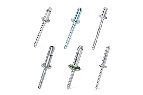
B. Measuring a Blind (Pop) Rivet (Uninstalled)
Blind rivets have both a rivet body (the sleeve) and a mandrel. The key dimensions are:
-
Rivet Body Diameter (Dₛ_body)
-
As above: measure the sleeve’s outer diameter (usually 2.4 mm, 3.2 mm, 4 mm, 4.8 mm, etc., in metric; or 3/32″, 1/8″, 5/32″ in imperial).
-
Technique: Calipers around the cylindrical section, just below the head.
-
-
Grip Range (Gₛ_min – Gₛ_max)
-
On Packaging: Blind rivets are sold with a specified grip range (e.g., 1.6–3.2 mm). Do not guess: always read the packaging or specification sheet.
-
Manually Estimating (if packaging is lost):
-
Measure the distance from the underside of head to the point where the mandrel begins to flare. This is an approximate maximum material thickness.
-
For the minimum grip: many blind rivets can clamp as little as ~80% of their stated minimum range, but this is unreliable without the original data. Always refer to manufacturer’s spec.
-
-
-
Head Style and Dimensions
-
Blind rivets often have a standard dome head (with an internal countersink lip). Measure head diameter and height the same way as solid rivets if the head style is critical to your application.
-
-
Mandrel Length and Break-Point
-
Less critical for selecting hole size—but if you plan to measure how far the mandrel protrudes: measure from the head’s top to the mandrel tip. Usually not needed unless you’re engineering a special blind setup.
-
4. Selecting the Correct Rivet Based on Your Measurements
Once you’ve gathered:
-
Dₛ (shank/sleeve diameter)
-
Lₛ (grip length under the head)
-
Dₕ (head diameter) and Hₕ (head height)
-
Gₛ (grip range for blind rivets)
you can match those to standard rivet tables:
| Shank Diameter | Common Head Dia. | Typical Head Height | Available Grip Lengths (Lₛ) | Head Styles |
|---|---|---|---|---|
| 2.4 mm | 4.8 mm | 1.5 mm | 3.2 – 6.4 mm | Dome, Countersunk |
| 3.2 mm | 6.4 mm | 2.0 mm | 3.2 – 9.5 mm | Dome, Countersunk, Large Flange |
| 4 mm | 7.6 mm | 2.5 mm | 6.4 – 12.7 mm | Dome, Countersunk |
| 4.8 mm | 8.8 mm | 3.0 mm | 6.4 – 15.9 mm | Dome, Countersunk |
Note: The table above is a generalized reference. Actual head diameters and heights vary slightly by manufacturer. Always confirm with the supplier’s data sheet.
-
Hole Size: Drill or punch a hole that equals the rivet’s shank diameter (Dₛ). If you measured a 4 mm rivet, use a 4.0 mm drill bit (or sometimes +0.1 mm clearance, depending on material hardness).
-
Grip Calculation: Sum the thicknesses of the pieces you want to fasten (e.g., 2 mm aluminum panel + 3 mm steel backing = 5 mm). Choose a rivet whose grip length (for solid rivets) or grip range (for blind rivets) encloses 5 mm.
-
Example: If you need to fasten 5 mm thickness, a 4 mm shank blind rivet with a grip range of 4.8–6.4 mm would be appropriate.
-
-
Head Style Considerations: If the fastened surface must be flush (e.g., a countersunk rivet in wood or thin sheet metal), measure the thickness of the head (so you can determine how much clearance remains once the head is seated). For a dome head where a slight protrusion is acceptable, simply verify that the head diameter (Dₕ) will cover the hole and that the head height (Hₕ) won’t interfere with nearby components.
5. Measuring an Installed Rivet (for Inspection)
Sometimes you need to verify that an installed rivet meets specifications (correct length driven, correct head sitting, etc.). Here’s how:
-
Measure Protruding Tail (Solid Rivets Only)
-
After driving a solid rivet (with a bucking bar or rivet gun), the “shop head” forms on the blind side. To check that the rivet was fully set: measure how far the tail protrudes. Ideally, it should be close to the original grip length minus the deformation thickness of the formed shop head.
-
Method: Put the riveted side face-down on a flat surface; use a feeler gauge or depth probe from the upside (head side) down to the protrusion. Compare against original nominal lengths.
-
-
Measure Head Seating (Blind Rivets)
-
Ensure the blind side bulge (mandrel span) is within acceptable range. Although not easy to measure once set, you can look for uniform bulge and that the mandrel has snapped at the correct break‐point.
-
Visual Check: A properly set blind rivet should have a symmetrical “flower” shape on the blind side and the mandrel stem should be flush or slightly recessed below the head.
-
-
Check Installed Grip (Clamping Force)
-
Use feeler gauges between the rivet head and the top sheet: there should be no gap if the grip length was correct. If you find space under the head, the rivet did not fully clamp—so the grip length was too long (or the hole oversize).
-
-
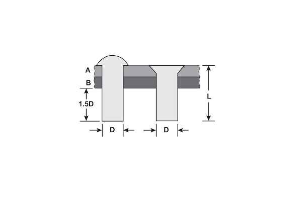
Head Diameter After Setting
-
On solid rivets, the shop head diameter (the formed “button” on the blind side) often expands to ~1.5× the original shank diameter. If you need to verify that expansion, measure across the widest bulged area with calipers.
-
6. Common Pitfalls & Tips
-
Hole Clearance Tolerance
-
Don’t assume the hole should always be exactly the same diameter as the rivet shank. For steel or hard materials, add +0.1 – 0.2 mm to the drill bit to ensure easy insertion without stress. Conversely, in plastics or soft metals, a snug (exact-fit) hole may be acceptable.
-
-
Countersunk vs. Dome Head Thickness
-
A countersunk rivet’s head is usually thinner and wider. When measuring length for a countersunk rivet, always measure from the underside of the countersunk chamfer, not from the very top of the angled head (which can skew length readings).
-
-
Metric vs. Imperial Confusion
-
If you find a rivet labeled “3/16″” (imperial), but your caliper reads 4.8 mm, record both measurements to avoid mismatch when ordering replacements—especially in international supply chains.
-
-
Grip Range Misunderstanding
-
Never choose a rivet whose minimum grip thickness is greater than your material stack. If your materials total 2 mm and the rivet’s grip range is 2.5 – 4 mm, it will not clamp properly (you’ll end up with a loose, wobbly joint).
-
-
Head Diameter vs. Clearance
-
Always check that the head diameter (Dₕ) will not interfere with adjacent features (holes, slots, edges). If the head is too large, it may overlap or prevent proper seating.
-
7. Practical Example
Let’s say you have a stack of two aluminum panels: one is 1.5 mm thick, the other is 2 mm thick. Total thickness = 3.5 mm.
-
Calculate Required Grip: 3.5 mm.
-
Choose Shank Diameter: You want moderate shear strength, so you pick a 4 mm rivet.
-
Select Grip Range: A common blind rivet size is 4 mm × 6 mm grip (4 mm shank, 6 mm grip range covers 2.4–4.8 mm). Since 3.5 mm is within 2.4–4.8 mm, that’s ideal.
-
Measure Rivet Dimensions to Confirm:
-
Shank: caliper reads 4.02 mm (±0.02 tolerance).
-
Head diameter: 7.6 mm (ensures coverage over the drilled hole).
-
Head height (dome): 2.5 mm.
-
-
Drill Hole: Use a 4.1 mm drill bit (slightly oversize to accommodate material crush and avoid jamming).
-
After Installation: The blind side shop head flares to about 6 mm diameter, clamping the panels. The mandrel snaps flush with the body.
8. Summary Checklist
When someone asks you, “How do you measure a rivet?” remember the following checklist:
-
Identify Head Style (dome, countersunk, large flange).
-
Use Calipers to Measure:
-
Shank (Body) Diameter (Dₛ)
-
Rivet Length (Lₛ): from underside of head to tip
-
Head Diameter (Dₕ)
-
Head Height (Hₕ)
-
-
For Blind (Pop) Rivets:
-
Verify grip range on packaging
-
Measure body diameter as above
-
Note mandrel break-point if needed
-
-
Match to Standard Charts: Compare your measurements to the manufacturer’s dimension tables to pick the correct nominal size.
-
Consider Material Thickness: Ensure chosen rivet’s grip length or grip range matches your material stack.
-
Account for Tolerances: Material hardness and hole clearance may require adding 0.1 – 0.2 mm to the drilled diameter.
-
Inspect After Installation (if measuring an installed rivet): Check gap under head, shop head bulge, and that the mandrel snapped correctly (for blind rivets).