Below is a step-by-step guide:
1. Gather the Tools You’ll Need
- Vernier calipers (digital or dial): Essential for measuring diameters and lengths to ±0.02 mm (±0.001″) accuracy.
- Thread pitch gauge (for metric pitches) or a thread picker/ruler (for imperial threads per inch—TPI).
-
Optional: a micrometer for even higher-precision diameter checks on very fine screws.
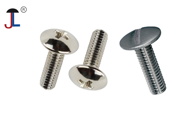
2. Identify the Type of Screw Head (Reference Purpose)
-
Before measuring, note the head style (e.g., socket‑head cap screw, pan head, flat head). While head style doesn’t affect the basic thread dimensions, it helps later to match replacement hardware or verify length measurements (for countersunk vs. non‑countersunk heads).
3. Measuring the Thread (Major) Diameter
- Zero your calipers fully closed.
- Place the caliper jaws around the screw’s threads—across the crests of the thread (not the valleys).
- Gently close until the jaws contact the crests on opposite sides but without compressing the threads.
-
Read the measurement:
- If you’re working in metric, you’ll see something like 5.00 mm, 6.00 mm, etc.
- If you’re working in imperial (inch‑based), you might see something like 0.138″ (which corresponds to a #6 screw at approximately 3.5 mm).
4. Measuring Thread Pitch (Metric) or TPI (Imperial)Tip: If measurement feels “loose” in the jaws, you might be measuring over the crest valleys instead of the crests. Rotate the screw slightly and verify you’re catching the true outer diameter of the thread.
-
Metric screws (pitch in millimeters):
- Use a metric thread pitch gauge. Each leaf is stamped with a specific pitch (e.g., 0.5 mm, 0.7 mm, 1.0 mm, 1.25 mm, etc.).
- Place the gauge leaf’s teeth into the screw’s threads. When the leaf sits flush across the face of the threads (no gaps or rocking), the number printed on that leaf is your screw’s pitch.
- That tells you “M × P”—for example, M4 × 0.7 means a 4 mm diameter screw with a 0.7 mm thread pitch (distance from one crest to the next).
-
Imperial screws (TPI—threads per inch):
- Use an imperial thread gauge (each leaf labeled with a TPI value—e.g., 20 TPI, 24 TPI, 32 TPI).
- Match the leaf to the threads in the same way: when it fits perfectly (no gaps), that leaf’s TPI is the screw’s pitch.
- Alternatively, you can place a ruler alongside the screw and count how many threads span exactly 1 inch (or scale it down: ½ inch and double it). But a gauge is more foolproof.
Example: If a leaf labeled “1.25 mm” fits perfectly on a 4 mm screw’s threads, that’s an M4×1.25.
5. Measuring Length
-
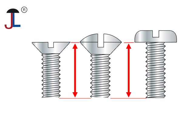
Length definition varies by head type:
- Countersunk (flat-head) screws: Measure from the top (flat surface) of the head down to the end of the threaded shaft.
- Raised or non‑countersunk heads (Pan, Button, Socket cap): Measure from the point where the head’s bearing surface meets the shank (i.e., the underside of the head) down to the tip of the threads.
- Zero your calipers on the depth rod or outside jaws (depending on your caliper style).
- Position the screw so you can measure from the skirt/underside of the head down to the tip of the threaded end.
- Read the length (e.g., “20 mm long” or “¾ inch long”).
Note: Some catalogs list length including a countersunk head’s thickness; others list only from the bearing surface. Always state explicitly: “Length measured from under-head to tip.”6. Verifying Thread Class/Tolerance (If Needed)
If you require an exact class (e.g., Class 2A vs. 3A in imperial, or 6H in metric), you may need a thread‑go/no‑go gauge set. For most practical purposes, simply matching diameter and pitch is sufficient. However, for high‑precision or safety‑critical applications, confirm thread class using calibrated gauges.
7. Checking Additional Details (Optional but Helpful)
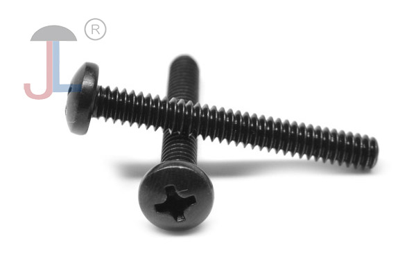
- Drive style: Slotted, Phillips, Torx, hex, etc. While this won’t change the diameter/pitch, know it when ordering replacements.
- Material/coating: Check if it’s stainless steel, zinc-plated alloy steel, etc. That doesn’t affect dimensions but matters for corrosion resistance and strength.
-
Shank length vs. threaded length: If the screw has an unthreaded shank portion, you might measure:
- Total length under head → tip.
- Threaded portion length separately (e.g., 12 mm of thread but overall length 20 mm).
Once you’ve measured:
-
Determine nominal diameter and pitch/TPI:
- Metric example: M5 × 0.8 (meaning 5 mm outer thread diameter, 0.8 mm pitch).
- Imperial example: ¼″‑20 (¼″ major diameter with 20 threads-per-inch).
- Specify length: Eg. “20 mm long” (under-head to tip) or “¾″ long” (for imperial).
- Specify head type and drive: Eg. “Socket‑head cap screw, M5×0.8×20, stainless steel, fully threaded” or “Flat‑head Phillips, ¼″‑20×¾″, zinc‑plated, coarse thread.”
- Optionally, note thread class: Eg. “Class 2A” (imperial) or “6H” (metric) if you need tighter tolerances.
Quick Reference Example (Metric)
- You measure outer thread crest diameter ≈ 6.0 mm.
- Thread gauge fits at 1.0 mm.
- Caliper measures 25 mm length from under-head to tip.
- Screw head is a countersunk flat‑head.
→ You have an M6 × 1.0 × 25 mm flat-head screw (likely with a 6H tolerance unless otherwise noted).
Quick Reference Example (Imperial)- You measure outer diameter ≈ 0.164″ (which is just under 5⁄32″ but closer to a #10 screw, whose actual major diameter is about 0.190″). If your caliper reads 0.190″, that’s a #10 major diameter.
- Your TPI gauge fits at 24 TPI.
- Length from under-head to tip is 1″ exactly.
- Head is a pan head with a Phillips drive.
→ You have a #10‑24 × 1″ pan-head Phillips screw, zinc‑plated.
Pro Tips & Common Pitfalls
- Avoid measuring at an angle. Always keep the caliper jaws perfectly perpendicular to the screw’s axis when measuring diameter.
- Thread damage can skew readings. If threads are galling or dinged, seek a fresh sample or inspect multiple spots until you find an undamaged section.
- Metric vs. imperial confusion. If your caliper gives you a decimal in inches (e.g., 0.138″), convert to fractional or hexadecimal as needed, but double-check against a standard chart (e.g., #6 = 0.1380″, #8 = 0.1640″, #10 = 0.1900″).
- Head type matters when specifying length. Countersunk heads require you to measure from the very top if the specification expects total head‑to‑tip. Most hardware suppliers assume “under‑head to tip.”
By following these steps—measuring major diameter with calipers, verifying pitch or TPI with a gauge, and carefully measuring length from the correct reference point—you’ll be able to identify (and order) an exact match whenever you need to replace or specify a machine screw.